A DIY Community for Tech, Science, and R&D
Join a culture of sharing, growth and collaboration. You can be a part of the maker movement!
The intention of this document is to get your familiar programming and using the Fipsy FPGA using a pre-built example – Blinky. The steps below will have you download the code, install the development tool, work with a project file, and upload the design to the FPGA.
This guide assumes let’s you program your device with either an ESP32, Rasberry Pi, or Arduino device. See more details on the programmers here.
The only version of the Fipsy FPGA that is available for purchase is the Fipsy FPGA V2. You can learn more about it here: https://www.fipsyfpga.com/about/fipsy-fpga-v2/
The materials you will need are:
Download the project files here:
You will need to install Lattice Diamond, which is free but requires an account.
http://www.latticesemi.com/latticediamond
You will install Lattice Diamond on your primary computer, and Lattice Diamond supports Windows or Linux. Later you will transfer output files from this program to your Fipsy FPGA by using a programmer.
When you open Lattice Diamond, select Open Project, and navigate to FipsyBaseline_DiamondProject
You will need to select a folder based on which verison of the Fipsy you have. Please select FipsyV2_XO2-1200 for the Fipsy V2 device.
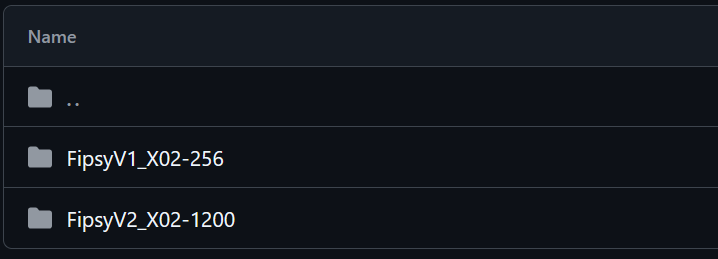
Open the template Project File – FipsyBaseline.ldf
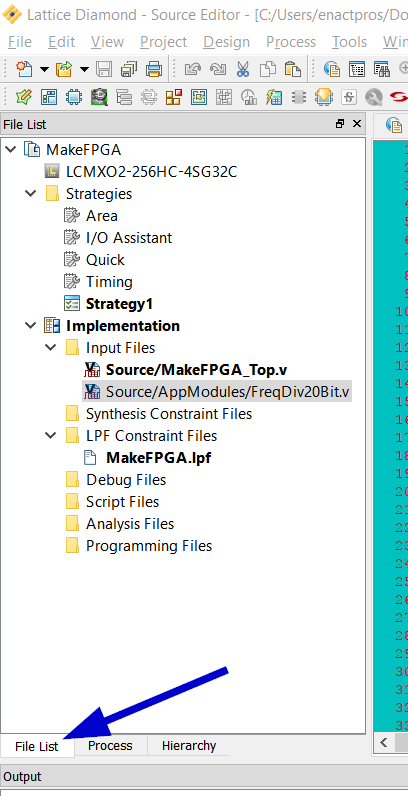
The file hierarchy can be found in the ‘File List’ tab:
The SPI port (slave) is how we will program the FPGA, and it MUST stay enabled always. It is possible to ‘Brick’ or disable all future reproggramming, if the SPI port is not enabled. If you upload a design with SPI disabled, you will NOT be able to reprogram the FPGA again. Always keep SPI enabled:
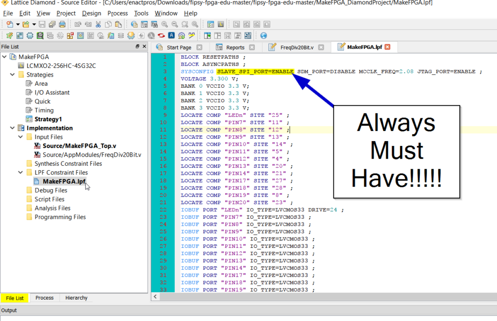
Under ‘LPF Constraint Files’ check that your .lpf file has:
SYSCONFIG SLAVE_SPI_PORT=ENABLE
The easiest way to ensure this, is build your projects off of the template project file provided here. The programmers we provide have some built in checks to make sure you have this enabled.
Click over to the next tab, and uncheck all boxes except the last one, JEDEC file. Right click and click RUN:
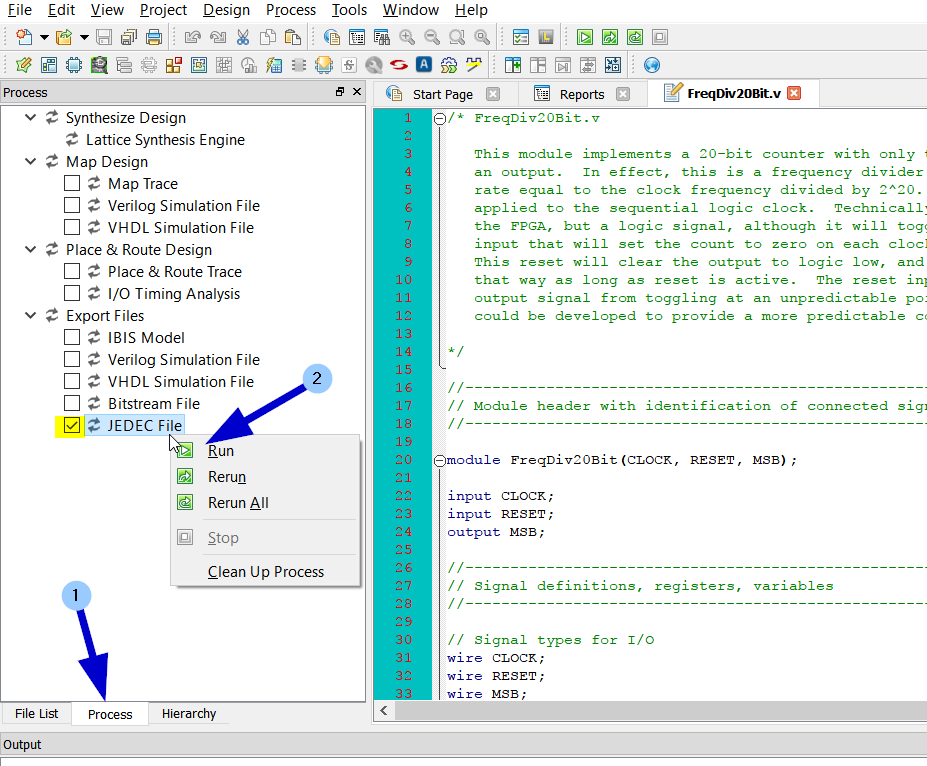
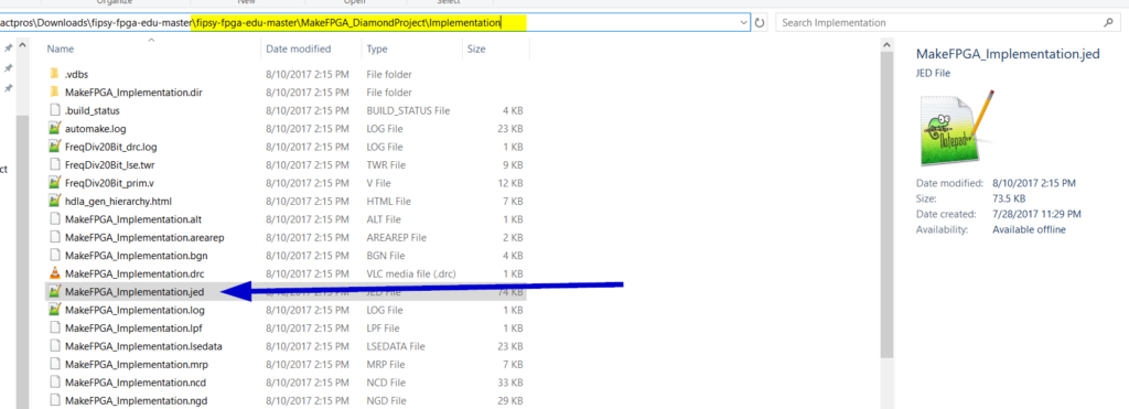
It will save a .jed file to the Implementations folder under the project folder:
Programming Options for the Fipsy FPGA.
Click to get more info about each.
You can use an ESP32 to program the Fipsy FPGA. Be aware that there are many variants of the ESP32 board, so some of the details below may be different. Both the ESP32 and the Fipsy FPGA operate at 3.3V and should be able to be connected to each other directly.
Here is the wiring we will need:
Fipsy ESP32
Pin 1 3.3V ← 3.3V
Pin 2 GND ← GND
Pin 3 SCK ← Pin D18 (SCK, in code set as pin 35)
Pin 4 MISO → Pin D19 (MISO, in code set as pin 38)
Pin 5 MOSI ← Pin D23 (MOSI, in code set as pin 36)
Pin 6 SS ← Pin D5 (SS, in code set as pin 34)
You will need to install the Arduino IDE – https://www.arduino.cc/en/software
Then you will need to make sure you can program your ESP32 in Arduino. Look around for guides for your specific device. We found this guide to be particularly useful:
https://randomnerdtutorials.com/installing-the-esp32-board-in-arduino-ide-windows-instructions/
See also, https://docs.espressif.com/projects/arduino-esp32/en/latest/installing.html
See how you can add ESP32 as an available board set (after adding the additional boards URLs – https://raw.githubusercontent.com/espressif/arduino-esp32/gh-pages/package_esp32_index.json )
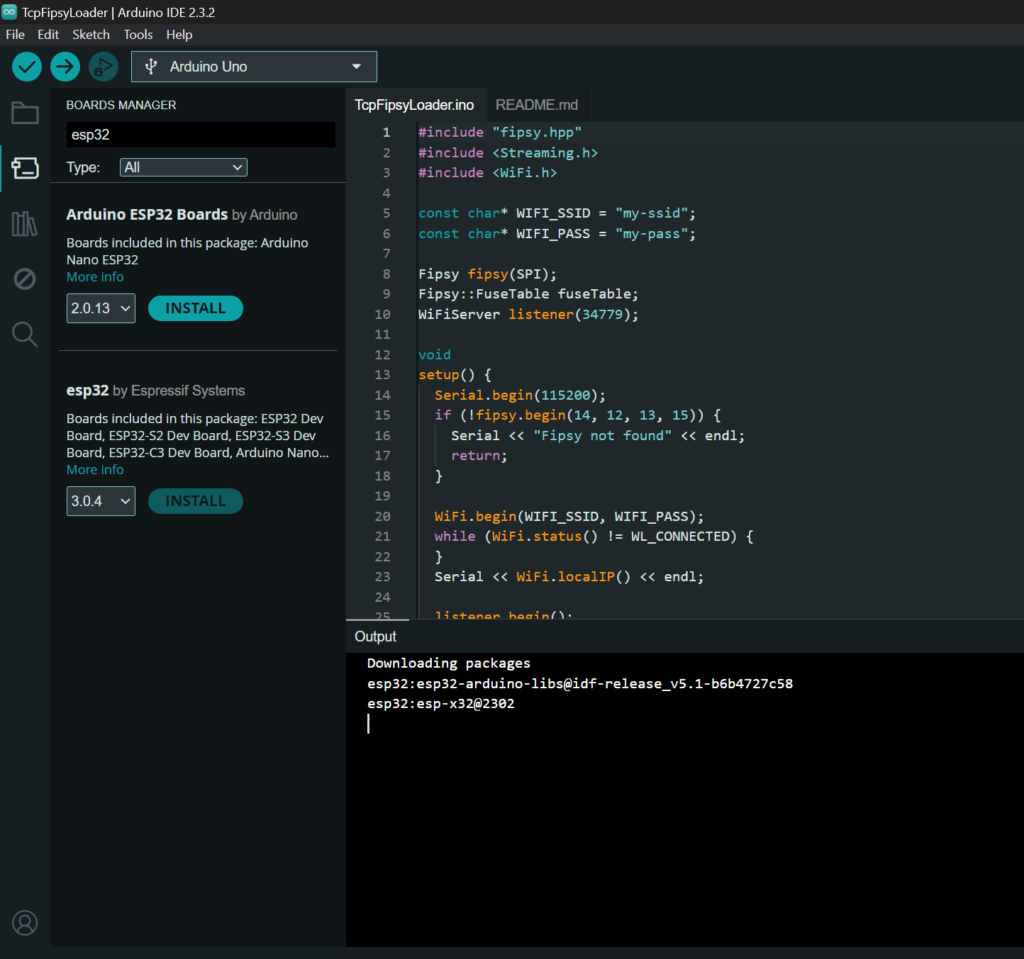
Before continuing, make sure you can push a simple program to your ESP32 via USB.
Grab the code from this repo:
https://github.com/MoCoMakers/esp-fipsy ( Forked from: https://github.com/yoursunny/esp-fipsy )
In particular open examples/TcpFipsyLoader/TcpFipsyLoader.ino in your Arduino IDE. This is the file you need to burn to your ESP32. To make it compile, you will need to upload an Arduino library that includes both:
esp-fipsy\src\fipsy.hpp
esp-fipsy\src\fipsy.cpp
See: https://github.com/MoCoMakers/esp-fipsy/tree/main/src
Create this as a .zip file, and it can be uploaded in the Arduino IDE:
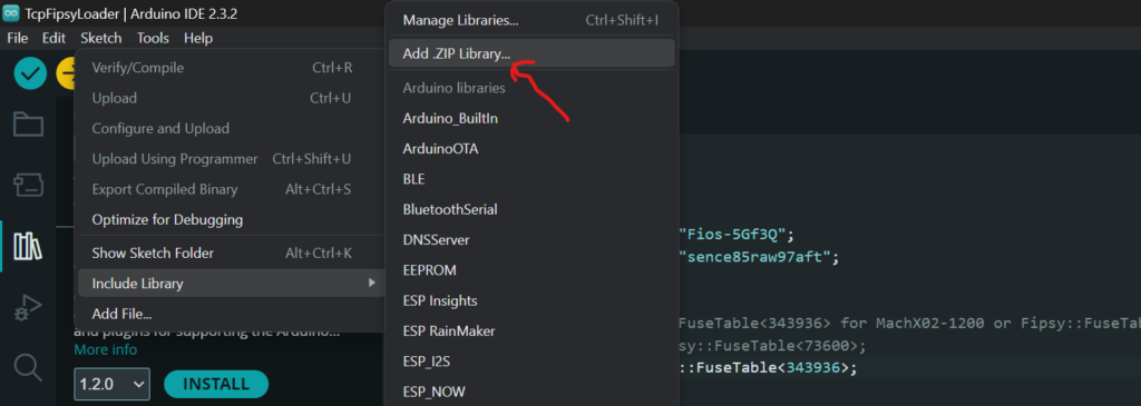
Once you have your .zip file, add it as a library to the TcpFipsyLoader.ino project by going to Sketch-> Include Library -> Add .ZIP Library.. (and selecting the .zip file you made).
At this time, verify that you can Compile the code successfully. If you still still have trouble see the Contact Us page for support tips.
Modify the following lines in your .ino file:
Add your WiFi details here:
const char* WIFI_SSID = "my-ssid";
const char* WIFI_PASS = "my-pass";
If you have Fipsy Ver 2 – use the Fipsy::FuseTable<343936> otherwise if you have the older, Fipsy Ver 1 use the other value.
// Choose either Fipsy::FuseTable<343936> for MachX02-1200 or Fipsy::FuseTable<73600> for MachXO2-256. These are the QF values from the .jed file.
//using FipsyClass = Fipsy::FuseTable<73600>;
using FipsyClass = Fipsy::FuseTable<343936>;
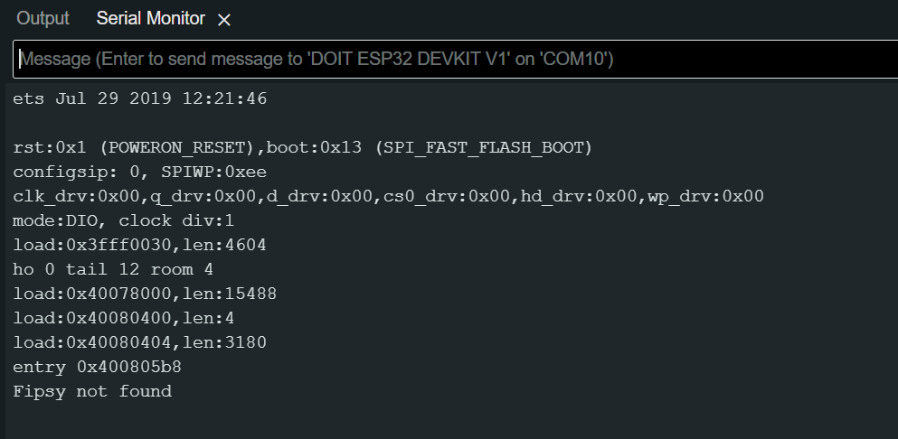
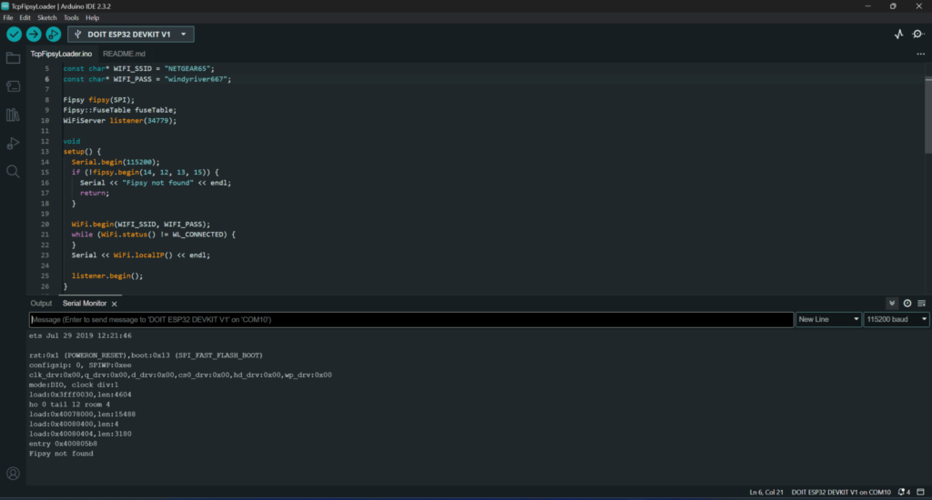
Now upload this code to the ESP32. You may need to press the “Boot” button for 3 seconds while it says “Connecting……” to initiate the firmware upload. Once the upload completes, switch to your Serial Monitor and you should see something like this (assuming your Fipsy is not connected).
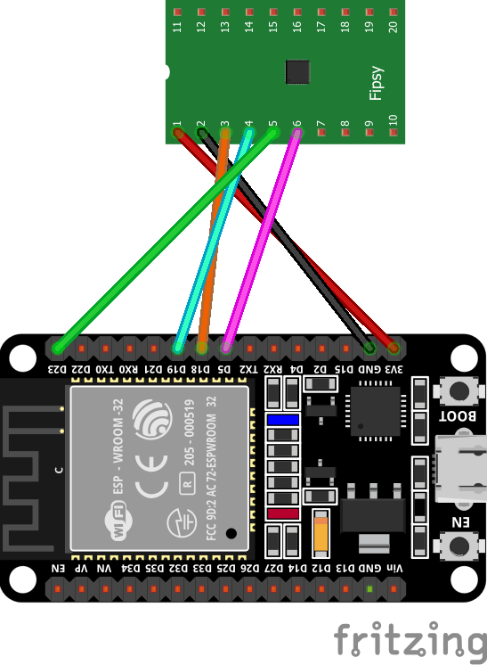
Connect your devices using jumper cables. I am using female-to-female jumpers.
Here is the wiring we will need:
Fipsy ESP32
Pin 1 3.3V ← 3.3V
Pin 2 GND ← GND
Pin 3 SCK ← Pin D18 (SCK, in code set as pin 35)
Pin 4 MISO → Pin D19 (MISO, in code set as pin 38)
Pin 5 MOSI ← Pin D23 (MOSI, in code set as pin 36)
Pin 6 SS ← Pin D5 (SS, in code set as pin 34)
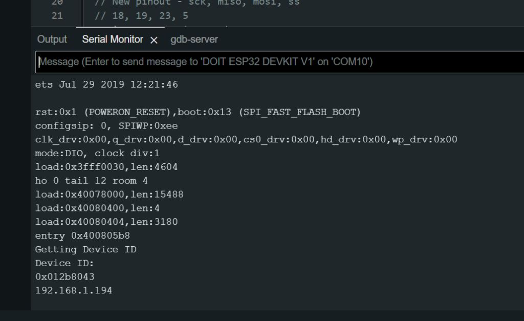
Once your device is wired (and ESP32 is still connected via USB in the Arduino IDE) – switch to your Serial Monitor. Tap on the “EN” button to reboot the device, and the following should be displayed. Notice how you will get an IP address – if you don’t double check that you wired your Fipsy properly, and uploaded a version of the ESP32 code that has your WiFi details (see above).
The recommended way to interact with your ESP32 programmer, is via WiFi using the sendJed.py script:
https://github.com/MoCoMakers/esp-fipsy/blob/main/scripts/sendJed.py
Do something similar to the following:
# Replace path with your project location
cd "C:\PATH\TO\Fipsy-FPGA-edu\FipsyBaseline_DiamondProject\FipsyV2_X02-1200\Implem
entation"

# Replace path, and IP Address. Arduino IDE's Serial Monitor will show the IP address on reboot of a programmed ESP32, as long as the wiring is correct (it will first try and fetch the device ID).
# Note also, your laptop needs to be on same WiFi as the ESP32, or you might get a timeout error with no useful message.

python "C:\PATH\TO\esp-fipsy\scripts\sendJed.py" 192.168.XXX.XXX --port 34779 --file 'C:\path\to\yourfile.jed' Note that above steps on this page show on how to create the FPGA configration .jed file (JEDEC file). Look for the file inside the Implementations folder of your project code after running the "JEDEC File" process in Lattice Diamond.
Instead of using the Python file, you can use an nccommand to send the file. The following instructions describe that alternative:
Our code will use the `nc` command exists in Linux, but not Windows by default. For Windows you should use Windows Subsystem for Linux (WSL2). For example you can install Ubuntu on Windows via the AppStore – https://apps.microsoft.com/detail/9pdxgncfsczv?hl=en-US&gl=US
Launch a command prompt that has the ‘nc’ command (this might be WSL in Windows).
Using the IP address from the previous step, use the `nc` command to upload your .jed file to your device. See the above steps on this page on how to create JEDEC file (.jed file, which will be generated inside the Implementations folder of your project code).
The README has more notes on this approach: https://github.com/MoCoMakers/esp-fipsy/tree/main/examples/TcpFipsyLoader
Run the following command to send your .jed file
nc esp32-ip-address 34779 < filename.jed
Note that you will need your Pi to be connected to the internet, otherwise, you will have to transfer the example files via USB.
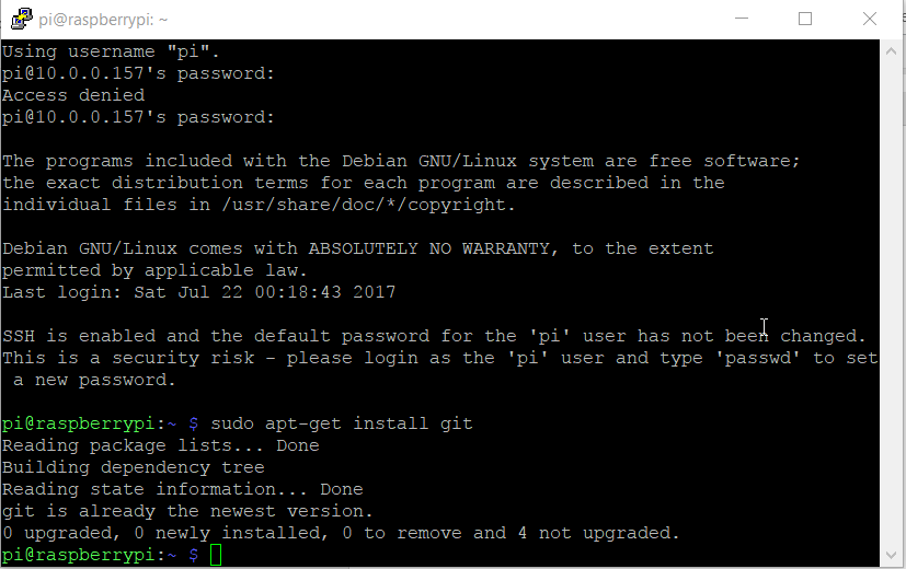
Install git with: sudo apt-get install git
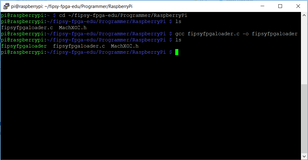
Type:
git clone https://github.com/MocoMakers/Fipsy-FPGA-edu
cd ~/Fipsy-FPGA-edu/Programmer/RaspberryPi
ls

gcc fipsyloader.c -o fipsyfpgaloader
ls
Move the executable to the user desktop (or the folder where you want to have your .jed output files)
cp ./fipsyfpgaloader ~/fipsyfpgaloaderCopy the JEDEC file (.jed) to the home directory:
cd ~/Fipsy-FPGA-edu/FipsyBaseline_DiamondProject/FipsyV2_X02-1200/Implementation/
# For Fipsy V1 X02-256 use the following instead:
# cd ~/Fipsy-FPGA-edu/FipsyBaseline_DiamondProject/FipsyV1_X02-256/Implementation/

cp FipsyBaseline_Implementation.jed ~/blinky2Hz.jedSPI is used to program the Fipsy FPGA, and it must be enabled on the Raspberry Pi.
On the Raspberry Pi type:
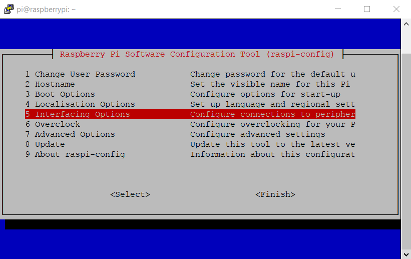
sudo raspi-configNext select ‘Interfacing Options’
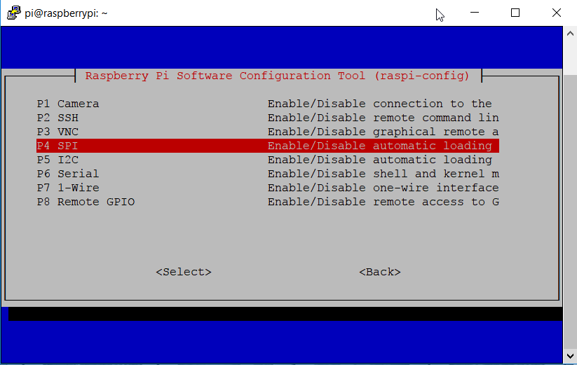
Go down to ‘SPI’ and select that option.
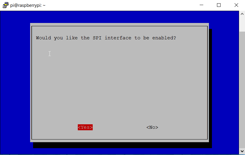
Select ‘Yes’ to enable the SPI
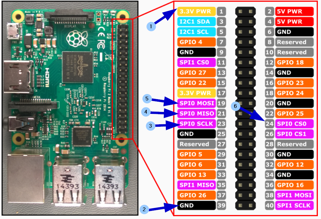
Fispy FPGA -> Rasberry Pi
Pin 1 -> 3.3V (GPIO 1)
Pin 2 -> GND (GPIO 39)
Pin 3 -> SCLK (GPIO 23)
Pin 4 -> MISO (GPIO 21)
Pin 5 -> MOSI (GPIO 19)
Pin 6 -> CS0 (GPIO 24)
On the raspberry pi type:
cd ~
./fipsyfpgaloader blinky2Hz.jed
You should see something like this, except with your own unique manufacturer ID (on the FPGA itself).
![14-Successful-Upload[1]](https://www.fipsyfpga.com/wp-content/uploads/2024/10/14-Successful-Upload1.png)
If you get all zeros for the Device ID, double check your wiring:
![15-Device-ID-zero-error[1]](https://www.fipsyfpga.com/wp-content/uploads/2024/10/15-Device-ID-zero-error1.png)
Congratulations, you are done!!
There are many ways to get what is essentially a text file onto the Raspberry Pi (from the Lattice project’s ‘Implementation’ folder).
The easiest way is via SFTP, see item 5 on this guide:
http://www.makeuseof.com/tag/copy-data-raspberry-pi-pc/
You may want to set up a shared folder, for another elegant solution:
Setting up a shared folder between Raspberry Pi and Windows:
www.mocomakers.com/rapid-programming-with-fipsy-on-the-raspberry-pi/
Note that the fipsyfpgaloader you compiled above in step 8 is an executable file. That means you can copy to a shared directory you set up. The command to copy the executable would be
cp /PATH_TO_FILE/fipsyfpgaloader /NEW/PATH/fipsyfpgaloaderYou could then change the the relevant folder:
cd /RELEVANT/PATH
and run the relevant ‘program FPGA’ command:
./fipsyfpgaloader NAME_OF_FILE.jedYou can use Arduino to program the Fipsy FPGA. However, be aware, MOST Arduino devices operated at 5 volts, which is enough to fry the 3.3 volt Fipsy device. This means a Logic Level Converter should be used:
Something like this:
https://www.sparkfun.com/products/12009
or this
We are working with 4 data lines with the SPI protocol. The devices above have an HV – high voltage reference, and an LV – low voltage reference, that defines the voltage that each side of the device operates at. Because we need a 3.3V reference voltage, we are supporting the Arduino Uno and Arduino Mega in particular (they have a very useful 3.3V output voltage pin).
Note that in a pinch you can get away with using only resistors to create a voltage level divider circuit, allowing 5V to talk to 3.3V devices (5 volts in to the Fipsy is bad, but 3.3V to a 5V device won’t hurt the 5V device, and should enough for 3.3V to 5V device communication). To figure out what resistors you’ll need use a Voltage Divider Calculator:
http://www.ohmslawcalculator.com/voltage-divider-calculator
Here is the wiring we will need:
Fipsy Arduino
Pin 1 3.3V ← 3.3V on Arduino Uno
Pin 2 GND ← GND
Pin 3 SCK ← [V Divider] ← Pin 13 (SCK)
Pin 4 MISO → Pin 12 (MISO)
Pin 5 MOSI ← [V Divider] ← Pin 11 (MOSI)
Pin 6 SS ← [V Divider] ← Pin 10 (SS)
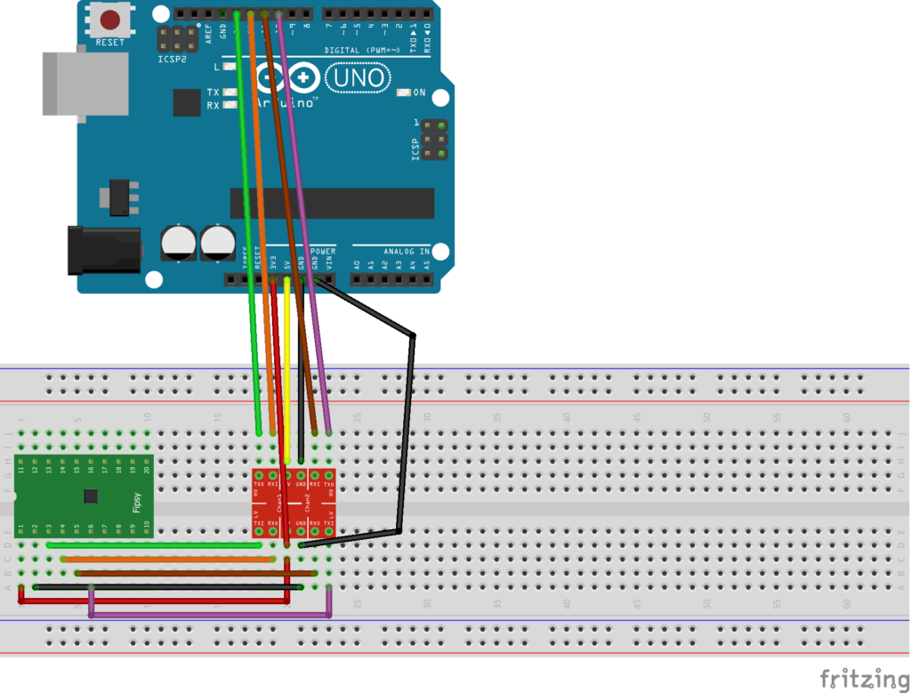
For now you need to run the code from command line (later we will add executables for all the major operating systems).
Download these files:
https://github.com/MocoMakers/Arduino-Fipsy-Programmer
You will need to install the Arduino IDE.
Install Python 3.1+
and Install a python module – PySerial
Open your Python 3.1+ and double-check that the following two commands work as intended:
from Tkinter import Tk
import serial
Upload the Arduino_Programmer.ino sketch to the Arduino.
Make sure you upload the ‘Arduino_Programmer.ino’ file to your Arduino – note that ‘MachXO2.h’ is a required dependency, so make sure its in the same folder as the .ino file.
Once this is done, keep the USB connected to the Arduino. Take note of what port your Arduino is using in the Arduino IDE, you will want to match that later.
From your command line, change directory to the location of your downloaded folder
For example:
cd C:\PATH\TO\Arduino-Fipsy-Programmer\Then run the script in python:
python FileChooser.pyFirst, select the port the Arduino is on from the drop down list (it should match the one in the Arduino IDE).
Next click ‘Check Device ID’.. you should get something like 01 DB 23 88, or a unique id for your device in the command line window. If you get:
FF FF FF FF, then there is a problem with the connection. Check you wiring, and try again.
Now select your .jed file created by Lattice Diamond using the ‘Select your file’ button (if you have one).
Click ‘Program Device’. Note this will erase your current configuration first, then program the new configuration.
Supplies are limited, but you can reach out to our manufacturer for a Windows USB programmer – the Backhauler:
https://store.alliedcomponentworks.com/products/backhauler-pmod-for-fipsy